


MODBUS/TCP is a derivative of the simple, vendor-neutral MODBUS series of communication protocols used to manage and control automation equipment. Obviously, it covers the use of MODBUS telegrams in "Intranet" and "Internet" environments using the TCP/IP protocol. The most common use of the protocol is for things like PLC's, I/O modules, and gateways to other simple domain buses or I/O modules.

1. What is the Modbus communication protocol
The MODBUS/TCP protocol was released as a (de facto) automation standard. Modbus communication protocol is a general communication protocol that has been widely used in today's industrial control field. Through this protocol, controllers can communicate with each other or with other devices via a network (eg, Ethernet). The Modbus communication protocol uses the master-slave communication technology, that is, the master device actively queries and operates the slave device. Generally, the protocol used by the master device is called Modbus Master, and the protocol used by the slave device is called Modbus Slave. Typical master devices include industrial computers and industrial controllers; typical slave devices such as PLC programmable controllers. Modbus communication physical interface can choose serial port (including RS232 and RS485) or Ethernet port. Its communication follows the following process:
1.1 The master device sends a request to the slave device
1.2 The slave device analyzes and processes the request of the master device, and then sends the result to the master device
1.3 If there is any error, the slave device will return an abnormal function code
2. The Modbus communication protocol has the following characteristics:
2.1 Standard and open, users can use the Modbus communication protocol for free and with confidence, without paying license fees and without infringing intellectual property rights. At present, there are more than 400 manufacturers supporting Modbus, and more than 600 products supporting Modbus.
2.2 Modbus can support a variety of electrical interfaces, such as RS-232, RS-485, etc., and can also be transmitted on various media, such as twisted pair, optical fiber, wireless, etc.
2.3 The frame format of Modbus is simple, compact and easy to understand. It is easy for users to use and easy for manufacturers to develop.
in decimal. Function codes can be divided into bit operations and word operations. The minimum unit of bit operation is BIT, and the minimum unit of word operation is two bytes.
[Bit operation command] Read coil state 01H, read (discrete) input state 02H, write single coil 06H and write multiple coils 0FH.
[Word operation instruction] Read holding register 03H, write single register 06H, write multiple holding registers 10H.
There are two acronyms to understand here: "ADU" and "PDU"
ADU: Application Data Unit
PDU: Protocol Data Unit
3. Two transmission modes of Modbus communication protocol
There are two commonly used MODBUS communication protocols, one is MODBUS ASCII and the other is MODBUS RTU. Each device must have the same transfer mode. All devices support RTU mode, ASCII transfer mode is an option.
3.1 ASCII transmission mode
When a device on a Modbus serial link is configured to communicate in ASCII mode, two ASCII characters are sent for every 8-bit byte in the message. Example: Byte 0X5B will be encoded as two characters: 0x35 and 0x42 for transmission (ASCII code 0x35="5", 0x42="B"), so the transmission efficiency will be reduced.
In ASCII mode, the message uses special characters to distinguish the start of the frame and the end of the frame. A message must start with a 'colon' (:) (ASCII hex 3A) and end with a 'carriage return-line feed' (CRLF) pair (ASCII hex 0D and 0A). The device continuously monitors the bus for the 'colon' character. When this character is received, each device decodes subsequent characters until the end of the frame. The time interval between characters in a message can be up to one second. If there is a larger interval, the receiving device considers that an error has occurred.
3.2 RTU transmission mode
When the device uses the RTU (RemoteTerminalUnit) mode to communicate on the Modbus serial link, each 8-bit byte in the message contains two 4-bit hexadecimal characters. The main advantage of this mode is higher data density and higher transmission efficiency than ASCII mode at the same baud rate. Each message must be transmitted in a continuous stream of characters.
4. Modbus communication protocol version
Versions of the Modbus communication protocol currently exist for serial, Ethernet, and other networks that support the Internet Protocol. Most Modbus device communication occurs through the serial EIA-485 physical layer.
For serial connections, there are two variants that differ slightly in numerical data representation and protocol details. Modbus RTU is a compact, binary representation of data, and Modbus ASCII is a human-readable, verbose representation. Both variants use serial communication. Subsequent commands/data in RTU format have a cyclic redundancy check checksum, while ASCII format uses a longitudinal redundancy check checksum. Nodes configured as the RTU variant will not communicate with nodes configured as the ASCII variant, and vice versa.
For connections over TCP/IP (eg Ethernet), there are several Modbus/TCP variants that do not require checksum calculations.
The data model and function calls are the same for all three communication protocols, only the encapsulation is different.
Modbus has an extended version, Modbus Plus (Modbus+ or MB+), but this protocol is proprietary to Modicon and is different from Modbus. It requires a specialized coprocessor to handle HDLC-like high-speed token rotation. It uses 1Mbit/s twisted pair, and each node has a conversion isolation device, which is a device that uses conversion/edge triggering instead of voltage/level triggering. Connecting Modbus Plus to a computer requires a special interface, usually a board that supports ISA (SA85), PCI or PMCIA bus.
5. Modbus communication protocol communication and equipment
The Modbus communication protocol is a master/slave architecture protocol. One node is the master node, and the other nodes participating in communication using the Modbus communication protocol are slave nodes. Each slave device has a unique address. In serial and MB+ networks, only the node designated as the master can initiate a command (on Ethernet, any device can send a Modbus command, but usually only one master device initiates a command).
A ModBus command contains the Modbus address of the device to be executed. All devices will receive the command, but only the device at the specified location will execute and respond to the command (except for address 0, the command specified at address 0 is a broadcast command, all devices that receive the command will run, but do not respond to the command). All Modbus commands contain check codes to ensure that incoming commands have not been corrupted. Basic ModBus commands can instruct an RTU to change a value in one of its registers, control or read an I/O port, and instruct the device to send back the data in one or more of its registers.
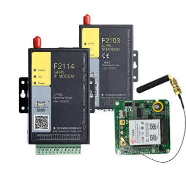
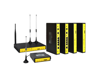
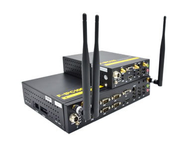
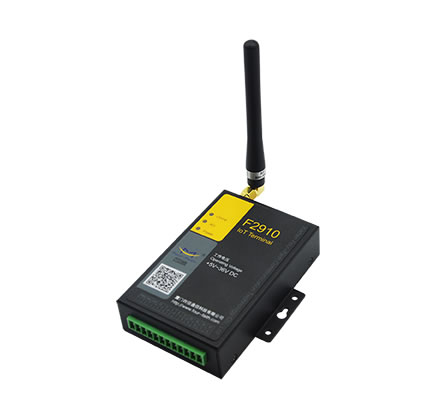
There are many modems and gateways that support the Modbus communication protocol because the Modbus communication protocol is simple and easy to replicate. Some of them are specially designed for this protocol. There are different implementations using wired, wireless communication and even short messaging and GPRS. However, designers need to overcome some issues including high latency and timing.
6. Modbus communication protocol restrictions
Modbus was developed for programmable logic controller communication in the late 1970s, these limited data types were understandable by PLCs in that era, large binary object data was not supported.
For nodes, there is no standard way to find the description of a data object, for example, to determine whether a register data represents a temperature between 30-175 degrees.
Since Modbus is a master/slave protocol, there is no way to ask a device to "report exceptions" (except for the TCP/IP protocol built on top of Ethernet, known as open-mbus) - the master node has to cyclically ask each node device, and look for changes in the data. In applications where bandwidth may be at a premium, this approach consumes bandwidth and network time in the application, such as on low-rate wireless links.
Modbus can only handle 247 addresses on a data link, which limits the number of devices that can be connected to the master site (again, with the exception of Ethernet TCP/IP), Modbus transmissions are buffered between remote communicating devices The way of data is carried out, there is a limit to the continuous communication, which avoids the problem of buffer loopholes in transmission. The Modbus communication protocol itself provides no security against unauthorized commands or intercepted data.
7. Modbus communication protocol implementation
Almost all implementations are some variant of the official standard. Correct communication between devices from different vendors may not be possible. Some of the major changes are:
7.1 Data types
IEEE standard floating point numbers
32-bit integer
8-bit data
mixed data types
bit fields in integers
multipliers to change data to/from integer. 10, 100, 1000, 256 ...
7.2 Protocol Extensions
16-bit slave address
32-bit data size (1 address = 32-bit data returned)
word exchange data