


In the video surveillance project, it is necessary to consider the power supply method of the camera. What kind of power supply method can achieve the best monitoring effect and save the project cost to the greatest extent? First of all, we need to understand several ways to supply power to cameras in video surveillance engineering.
What are the power supply methods for the camera?
1. Centralized power supply
Centralized power supply refers to the way that the source equipment is installed in the power room and the battery room, and the communication power is uniformly transformed and distributed to supply power to each communication equipment.
The advantages of the centralized power supply scheme lie in the unified control and management of the power supply scheme, reducing the use of engineering cables, and beautifying the engineering wiring and routing. However, please note that when using the centralized power supply scheme, it should be ensured that the total capacity of the centralized power supply equipment is greater than the sum of the service capacity of each load at the subsequent stage. At the same time, it is also necessary to consider that the wire diameter of the front-stage cable should meet the current capacity and wire diameter requirements of all loads in the latter stage.
Centralized power supply: connect a 12V centralized power supply at the 220V power supply, and then connect the 2*1.0 red and black power cables to the camera respectively. The 12V power supply distance cannot exceed 100 meters. After connecting a single power cord connector, connect the single power cord connector to the surveillance camera power connector. The centralized power supply mode refers to the centralized power supply to the front-end load using a 12V switching power supply in the monitoring room or a certain intermediate point.
1.1 Advantages: convenient construction, easy maintenance, unified control and management.
1.2 Disadvantages: The transmission distance of DC low-voltage power supply is too long, the voltage loss is high, and the anti-interference ability during transmission is poor.
2. Point-to-point power supply
Point-to-point power supply refers to direct 220V AC power from the monitoring room, connect a separate DC12V power supply next to the camera, then connect it to the monitoring camera, and install the bracket.
2.1 Advantages: 220V AC has low voltage loss during transmission and strong anti-interference ability.
2.2 Disadvantages: A power supply must be installed at each point, and the construction is more troublesome.
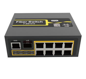
3. PoE power supply
PoE power supply refers to the technology of providing DC power supply to other devices without making any changes to the existing Ethernet Cat.5 cabling infrastructure. This method is mainly used in high-definition network digital monitoring systems.
3.1 Advantages: Cost reduction, flexible deployment, and the maximum power of a single port can reach 30W.
3.2 Disadvantages: High requirements for network cable quality and limited transmission distance.
How many volts does the camera supply
Cameras generally use 12VDC DC power supply, dome cameras generally use 24VAC AC power supply, some cameras use 220V AC power supply directly, and some home network cameras are only powered by 5V.
What is the best way to power the camera
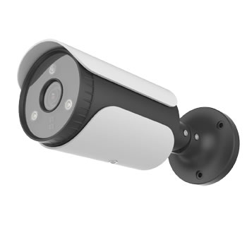
1. When using an infrared camera, it is not recommended to use a centralized power supply method. Because the current is relatively large when the infrared is turned on, it is difficult to ensure the infrared effect of all cameras in the centralized power supply method.
2. The point-to-point power supply and the nearby power supply can save the line, which is a great saving, but after-sales maintenance and maintenance are extremely difficult; this is for sure, centralized power supply has an advantage, and it is easy to maintain and release in the future, and it is not easy to cause problems. But if you don't cut the wire, if you slap your butt and leave after finishing this order, then you can use point-to-point power supply. For long-term, it is better to use centralized power supply.
3. If there are many sockets, use separate ones to get electricity nearby. If there are not many sockets, you can use centralized ones; if you are indoors, you can use a better sheathed power cord.
4. When the number of cameras is large and the power supply distance is less than 100 meters, it is recommended to use PoE power supply, which is convenient and fast without special construction, but pay attention to the selection of PoE power supply equipment.
Introduction to Power over Ethernet Standard
The publication of the IEEE standard for Power over Ethernet (PoE) in June 2003 has become a favorable condition for the development of Internet Protocol (IP) equipment. Delivering the 13W of power and data required by dedicated devices simultaneously over Ethernet lowers the barrier to entry and makes a very expensive solution feasible. The installation of infrastructure for devices such as IP cameras, wireless access points or IP phones has become as simple as cutting a wire in a punch block.
PoE hardware can be divided into two types: devices that provide power to the Ethernet link and devices that consume power. The device that supplies power to the link is called a Power Sourcing Equipment (PSE), and the Powered Device (PD) is an equally well-understood name, the device that consumes power on an Ethernet link. This paper combines the two to best evaluate PSE and PD, respectively.
Power over Ethernet seems like a trivial technology. Standard telephones have provided both power and data in the same wiring for over a hundred years. But for Ethernet, before people wanted to add power to it, there was already a very large market. Every single piece of equipment deployed could be damaged or destroyed if voltages were applied to existing Ethernet cables. To avoid this shortcoming, the task group that wrote the standard developed a measure to protect the device so that electricity could be applied to the device.
The detection procedure is performed by the PSE before applying voltage to the link. The PSE detects the link using at least two low-voltage and current-limit levels, looking for the PD's special signature (which is a 25KΩ resistive slope). These signals should be between 2.8V and 10V and are not capable of supplying more than 5mA. Under certain conditions, the standard requires only two test probes to turn an invalid signature into a valid signature. Current best practice uses three (sometimes four) independent probe signals, which is the number of probe signals allowed by the standard.
If the PSE successfully detects a PD, then it may power the link. If the PSE is not powering the link, it must do the same test again within 400ms, or run the test all the time. Once the link is successfully powered, the PSE must monitor the link to ensure that neither an overcurrent event occurs nor that the power required by the PD is available. The occurrence of overcurrent is almost certainly either a faulty wiring or a faulty PD. However, the PD may no longer require power because the user has tied the PD to a local power source or disconnected the PD from the link. PoE can't figure out if the PD is disconnected from the link or if it "doesn't need" power, but the end result is the same, the PSE will no longer supply power to that port.
In addition to detecting power to the PD, the PSE may also attempt to ask the PD how much power it needs through a process called "sorting." While not required by normative standards, most PDs provide useful classification information, roughly categorizing them as: 1/4, half or full power operating devices. The PSE uses this information to efficiently allocate its power.
On the PD side of the cable, the situation is almost the same. When PD detects and inputs 2.7V~10.1V voltage, it must be connected with a 25KΩ load. If the input range of the PD is 14.5V to 20.5V, then the PD will be connected to a constant current load which will show the power consumed by the PD. Note that reporting classification information through this current load is optional. However, every integrated PD chip on the market today supports this feature and the information reported is very useful. Once the voltage range of the input port is between 36V~42V, the PD power supply will be turned on; when the voltage of the input terminal falls back to 36V~30V, the PD power supply will be turned off. Unlike PSE, there is no requirement to follow state continuity in PD. PD is a purely voltage-driven function.
Real-world applications and engineers designing for them must be concerned with issues such as surge protection, noise immunity, and emission spectrum. However, the IEEE specification does not include certain isolation requirements, which should not be confused with the security requirements of the target market for the end equipment. These requirements go well beyond the scope of the IEEE PoE specification and are addressed by other regulations and requirements. The notable exception is that the IEEE specification does not require the PSE to meet the requirements for limited power supplies.