

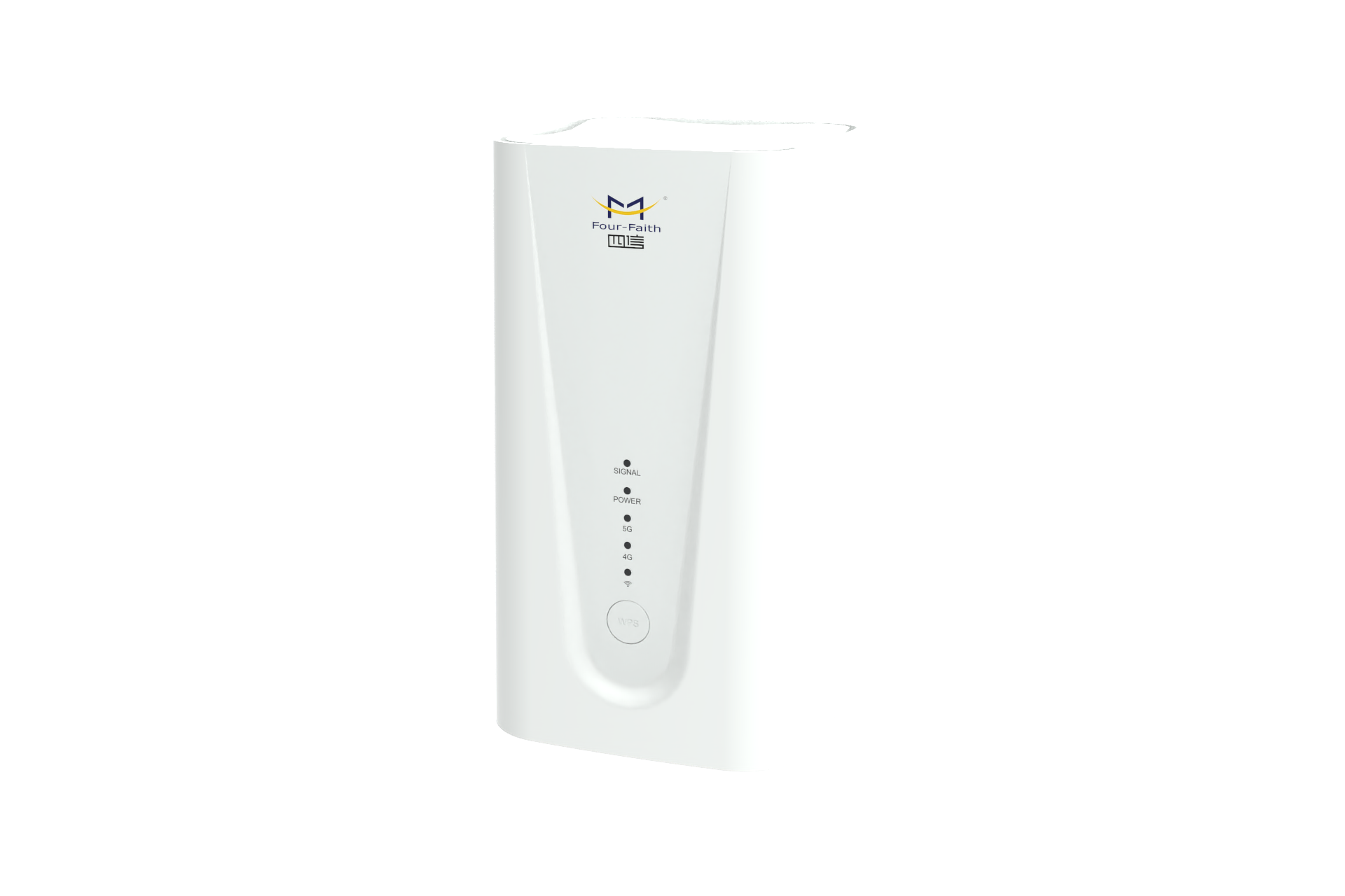
A router is a device that connects various local area networks and wide area networks in the Internet. It will automatically select and set routes according to the channel conditions, and send signals in the best path and in sequence. The router is the hub of the Internet, the "traffic police". At present, routers have been widely used in all walks of life, and various products of different grades have become the main force for realizing the internal connection of various backbone networks, the network interconnection between backbone networks, and the interconnection between backbone networks and the Internet.
1. Network interconnection
Interconnecting one's own network with other networks, obtaining more information from the network and publishing one's own news to the network are the main driving forces for network interconnection. There are many ways to interconnect the network, among which bridge interconnection and router interconnection are the most used.
1.1 Networks interconnected by bridges
Bridges work at the second layer in the OSI model, the link layer. Complete data frame (frame) forwarding, the main purpose is to provide transparent communication between connected networks. The forwarding of the bridge is based on the source address and destination address in the data frame to determine whether a frame should be forwarded and to which port. The address in the frame is called the "MAC" address or "hardware" address, which is generally the address carried by the network card.
The role of a bridge is to interconnect two or more networks to provide transparent communication. Devices on the network cannot see the existence of the bridge, and the communication between devices is as convenient as on a network. Since the bridge is forwarded on the data frame, it can only connect the same or similar networks (data frames of the same or similar structure), such as between Ethernet, between Ethernet and token ring (token ring) Interconnection, for different types of networks (with different data frame structures), such as between Ethernet and X.25, the bridge is powerless.
The network bridge expands the scale of the network, improves the performance of the network, and brings convenience to the network application. In the previous network, the network bridge was widely used. However, bridge interconnection also brings a lot of problems: one is broadcast storm, the bridge does not block broadcast messages in the network, when the network is large (several bridges, multiple Ethernet segments), it may cause A broadcast storm causes the entire network to be filled with broadcast information until it is completely paralyzed. The second problem is that when interconnecting with an external network, the bridge will combine the internal and external networks into one network, and both parties will automatically fully open their network resources to each other. This type of interconnection is obviously unacceptable when interconnecting with external networks. The main source of the problem is that bridges only maximize network communication, regardless of what information is being sent.
1.2 Router interconnection network
The interconnection of routers is related to the protocol of the network, and our discussion is limited to the case of TCP/IP networks.
Routers work in the third layer of the OSI model, the network layer. The router uses the "logical" network address (ie IP address) defined by the network layer to distinguish different networks, realize the interconnection and isolation of networks, and maintain the independence of each network. Routers do not forward broadcast messages, but limit broadcast messages within their respective networks. Data sent to other networks is first sent to the router, and then forwarded by the router.
IP routers only forward IP packets, and block the rest of the network (including broadcast), so as to maintain the relative independence of each network, which can form a large network with many networks (subnets) interconnected. Due to the interconnection at the network layer, routers can easily connect different types of networks. As long as the network layer runs the IP protocol, they can be interconnected through routers.
Devices on a network communicate with each other using their network addresses (IP addresses in TCP/IP networks). IP addresses are "logical" addresses independent of hardware addresses. Routers only forward data based on IP addresses. The structure of the IP address has two parts, one part defines the network number, and the other part defines the host number within the network. At present, the subnet mask is used in the Internet network to determine the network address and the host address in the IP address. The subnet mask and IP address are also 32 bits, and the two are in one-to-one correspondence, and it is stipulated that the part of the IP address corresponding to the number "1" in the subnet mask is the network number, and the part of the IP address corresponding to the number "0" is the network number. The corresponding host number. The network number and the host number together constitute a complete IP address. The IP addresses of hosts in the same network must have the same network numbers. This network is called an IP subnet.
Communication can only be carried out between IP addresses with the same network number. To communicate with hosts on other IP subnets, it must go through a router or gateway on the same network. IP addresses of different network numbers cannot communicate directly, even if they are connected together, they cannot communicate.
Routers have multiple ports for connecting multiple IP subnets. The network number of the IP address of each port is required to be the same as the network number of the connected IP subnet. Different ports are different network numbers, corresponding to different IP subnets, so that the hosts in each subnet can send the required IP packets to the router through the IP addresses of their own subnets.
2. System composition
From the architectural point of view, routers can be divided into the first-generation single-bus single-CPU structure router, the second-generation single-bus master-slave CPU structure router, the third-generation single-bus symmetric multi-CPU structure router; the fourth-generation multi-bus multi-CPU structure router Fabric routers, fifth-generation shared-memory fabric routers, sixth-generation crossbar architecture routers, and cluster-based routers.
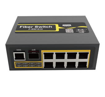
A router has four elements: input ports, output ports, switches, route processors, and other ports.
The input port is the physical link and the entry point of the input packet. Ports are usually provided by line cards, a line card typically supports 4, 8 or 16 ports, and one input port has many functions. The first function is to perform data link layer encapsulation and decapsulation. The second function is to look up the destination address of the incoming packet in the forwarding table to determine the destination port (called route lookup). The route lookup can be implemented using general hardware, or by embedding a microprocessor on each line card. . Third, in order to provide QoS (Quality of Service), the port classifies the received packets into several predefined service levels. Fourth, the ports may need to run data link-level protocols such as SLIP (Serial Wire Internet Protocol) and PPP (Point-to-Point Protocol) or network-level protocols such as PPTP (Point-to-Point Tunneling Protocol). Once the route lookup is complete, a switch must be used to route the packet to its output port. If the router is input-queued, there are several inputs that share the same switch. The final function of such an input port is to participate in an arbitration agreement on a common resource such as a switch.
Swap switches can be implemented using a number of different techniques. By far the most used switch technology is bus, crossbar and shared memory. The simplest switches use a single bus to connect all input and output ports. The disadvantage of bus switches is that their switching capacity is limited by the capacity of the bus and the additional overhead of arbitration for a shared bus. Crossbars provide multiple data paths through switches, and a crossbar with N×N crosspoints can be thought of as having 2N buses. If a cross is closed, the data on the input bus is available on the output bus, otherwise it is not available. The closing and opening of the intersection is controlled by the scheduler, therefore, the scheduler limits the speed at which the switches can be exchanged. In a shared memory router, incoming packets are stored in shared memory, and only pointers to the packets are exchanged, which increases the switching capacity, but the speed of switching is limited by the memory access speed. Although memory capacity can double every 18 months, memory access time decreases by only 5% per year, an inherent limitation of shared memory switches.
The output port stores packets before they are sent to the output link, and can implement complex scheduling algorithms to support requirements such as priority. Like input ports, output ports must also support data link layer encapsulation and decapsulation, as well as many higher-level protocols.
The route processor computes the forwarding table to implement the routing protocol and runs the software that configures and manages the router. At the same time, it also handles those packets whose destination address is not in the forwarding table of the line card.
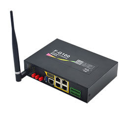
Other ports generally refer to control ports. Since the router itself does not have input and terminal display devices, it needs to be configured properly before it can be used normally. Therefore, general routers have a control port "Console", which is used to communicate with computers or computers. The terminal equipment is connected, and the router is configured through specific software. A console port is installed on all routers, allowing users or administrators to use a terminal to communicate with the router to complete the router configuration. This port provides an EIA/TIA-232 asynchronous serial interface for local configuration of the router (first configuration must be done through the console port).
The console port is directly connected to the serial port of the computer using a dedicated configuration line, and the local configuration of the router is performed by using a terminal emulation program (such as "Hyper Terminal" under Windows). The console ports of routers are mostly RJ-45 ports. The figure below contains a Console configuration port.