


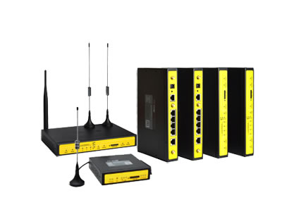


The router plays an important role in the computer network and is the bridge of the computer network. It can not only connect different networks, but also choose the path of data transmission and block illegal access.
Router configuration and debugging: Router configuration is not very easy for beginners. Now I will introduce the general configuration and simple debugging of the router to you for reference when configuring the router. This article takes Cisco2501 as an example.
Cisco2501 has one Ethernet port (AUI), one Console port (RJ45), one AUX port (RJ45) and two synchronous serial ports, supports DTE and DCE equipment, supports EIA/TIA-232, EIA/TIA-449, V. 35, X.25 and EIA-530 interfaces.

1. Router Configuration
1.1 Configuring the Ethernet port
# conf t (configure router from terminal)
# int e0 (specify port E0)
# ip addr ABCD XXXX (ABCD is the Ethernet address, XXXX is the subnet mask)
# ip addr ABCD XXXX secondary (E0 port supports two address types at the same time. If the first one is a class A address, the second one is a class B or class C address)
# no shutdown (activate E0 port)
# exit
After completing the above configuration, use the ping command to check whether the E0 port is normal. If it is not normal, it is generally because the port is not activated, and beginners tend to ignore it. Use the no shutdown command to activate the E0 port.
1.2 Configuration of X.25
# conf t
# int S0 (specify S0 port)
# ip addr ABCD XXXX (ABCD is the IP address of Ethernet S0, XXXX is the subnet mask)
# encap X25-ABC (encapsulates the X.25 protocol. ABC specifies X.25 as DTE or DCE operation, the default is DTE)
# x25 addr ABCD (ABCD is the X.25 port address of S0, provided by the post and telecommunications bureau)
# x25 map ip ABCD XXXX br (mapped X.25 address. ABCD is the IP address of the opposite router (eg: S0), XXXX is the X.25 port address of the opposite router (eg: S0))
# x25 htc X (Configure the highest number of bidirectional channels. The value range of X is 1-4095, which should be configured according to the actual number provided by the post and telecommunications bureau)
# x25 nvc X (configure the number of virtual circuits, X cannot exceed the number actually provided by the post and telecommunications bureau, otherwise it will affect the normal transmission of data)
# exit
After the configuration of the S0 port is completed, use the no shutdown command to activate the E0 port. If the ping S0 port is normal, and the X.25 IP address mapped by ping, that is, the IP address of the router port of the other party is not available, it may be caused by the following situations: 1) The X.25 address configuration of the local machine is incorrect, and re-check with the post office (X. 25 address length is 13 bits); 2) The mapping IP address or X.25 address of the local machine is incorrectly configured, and the reconfiguration is correct; 3) The other party's IP address or X.25 address configuration is incorrect; 4) The local machine or the other party's routing configuration is incorrect.
Can communicate with the other party, but there is packet loss phenomenon. In this case, there are generally the following possibilities: 1) The line condition is not good, or the network card and RJ45 plug are in poor contact; 2) The value range of the maximum number of bidirectional channels X of x25 htc and the number of virtual circuits X of x25nvc exceed the actual provision of the post and telecommunications office numbers. The higher the maximum number of bidirectional channels and the number of virtual circuits, the better, but must not exceed the numbers actually provided by the post and telecommunications bureau, otherwise packet loss will occur.
1.3 Leased line configuration
# conf t
# int S2 (specify S2 port)
# ip addr ABCD XXXX (ABCD is the IP address of S2, XXXX is the subnet mask)
# exit
After the dedicated line port configuration is complete, use the no shutdown command to activate the S2 port.
1.4 Configuration of Frame Relay
# conf t
# int s0
# ip addr ABCD XXXX (ABCD is the IP address of S0, XXXX is the subnet mask)
# encap frame_relay (encapsulate frame_relay protocol)
# no nrzi_encoding (NRZI=NO)
# frame_relay lmi_type q933a (LMI uses the Q933A standard. There are three types of LMI (Local management Interface): ANSI: T1.617, CCITTY: Q933A and Cisco-specific standards)
# frame-relay intf-typ ABC (ABC is the frame relay device type, which are supported by DTE devices, DCE switches or NNI (network point interfaces) respectively)
# frame_relay interface_dlci 110 br (configure DLCI (Data Link Connection Identifier))
# frame-relay map ip ABCD XXXX broadcast (establish frame relay mapping. ABCD is the IP address of the other party, XXXX is the local DLCI number, broadcast allows broadcast forwarding or updating routes)
# no shutdown (activate this port)
# exit
After the frame relay S0 port is configured, use the ping command to check the S0 port. If it is not normal, usually because the port is not activated, use the no shutdown command to activate the S0 port. If the ping S0 port is normal, but the IP address mapped by ping is abnormal, it may be that the frame relay switch or the other party is misconfigured. Comprehensive investigation is required.
1.5 Configure synchronous/asynchronous port (applicable to 2522)
# conf t
# int s2
# ph asyn (configure S2 as asynchronous port)
# ph sync (configure S2 as a sync port)
1.6 Configuration of Dynamic Routing
# conf t
# router eigrp 20 (using EIGRP routing protocol. Common routing protocols include RIP, IGRP, IS-IS, etc.)
# passive-interface serial0 (if S0 is connected to X.25, enter this command)
# passive-interface serial1 (if S1 is connected to X.25, enter this command)
# network ABCD (ABCD is the Ethernet address of the machine)
# network XXXX (XXXX is the IP address of S0)
# no auto-summary
# exit
1.7 Configuration of static routes
# ip router ABCD XXXX YYYY 90 (ABCD is the Ethernet address of the peer router, XXXX is the subnet mask, and YYYY is the corresponding WAN port address of the peer)
# dialer-list 1 protocol ip permit
2. Comprehensive debugging
After all the routers are configured, a comprehensive debugging can be carried out.
2.1 First activate the router's Ethernet port and all serial ports to be used. The method is to enter the port and execute no shutdown.
2.2 Add the default route (the Ethernet address of the central router) to the host connected to the router. The method is to execute under the super user of the Unix system: router add default XXXX 1 (XXXX is the E0 port address of the router). Each host must add a default route, otherwise, it will not be able to communicate normally.
2.3 Ping the Ethernet port of the router of the machine. If it fails, the Ethernet port may not be activated or not on a network segment. Ping the WAN port, if it fails, no default route is added. Ping the other party's WAN port. If it fails, the router configuration is wrong. Ping the Ethernet port of the host, if it fails, the host of the other party has not added a default route.
2.4 Add a gateway (static route) to the X.25 host of the dedicated line card. The method is to execute it under the super user of the Unix system: router add X.X.X.X Y.Y.Y.Y 1 (X.X.X.X is the Ethernet address of the other party, and Y.Y.Y.Y is the wide area network address of the other party).
2.5 Use Tracert to trace the route to determine the unreachable network segment.